
Sign In
Welcome! Sign In to personalize your Cat.com experience
If you already have an existing account with another Cat App, you can use the same account to sign in here
Register Now
One Account. All of Cat.
Your Caterpillar account is the single account you use to log in to select services and applications we offer. Shop for parts and machines online, manage your fleet, go mobile, and more.
Account Information
Site Settings
Security
Cat® Internally Excited (IE) Alternators
Roger Rosborough
Electric Power, Caterpillar Inc.
ABSTRACT
What is an Internally Excited (IE) alternator and how does it perform?
This paper will provide you with a detailed description of IE and demonstrate how the Cat® SR5 IE performance can be considered as identical to permanent magnet (PM) excitation, including the provision of permanent magnet inserts to obviate concerns of loss of residual magnetism.
INTRODUCTION
There are three basic sources for alternator excitation energy; Self Excited (SE), Internally Excited (IE) and Permanent Magnet (PM). SE is the most basic excitation type with a limitation on short circuit capability and is sometimes referred to as Shunt excitation. The limitation of the SE can be overcome by adding a permanent magnet generator (PMG) to the end of the SE alternator, which converts it to PM excitation. The PMG supplies power to the voltage regulator, which allows current to be delivered by the alternator even though its terminals are shorted. More detailed information on the basics of excitation is available from the Caterpillar white paper, LEXE1643 “Excitation Selections.”
The focus of this discussion is on IE, which is an alternative method for supplying an external source of energy to the excitation system, while providing comparable performance to PM excitation. IE is sometimes referred to as “auxiliary winding regulation excitation principle” or AREP. All Cat SR5 alternators are either IE or PM.
IE OPERATION
The IE system provides equivalent short-circuit performance to the PM excitation. It consists of two additional sets of coils which are inserted in certain slots of the main stator. The IE winding is electrically isolated from the main stator winding and is sealed within the stator during the insulation process, the IE windings can be seen in Figures 1 and 2 below.
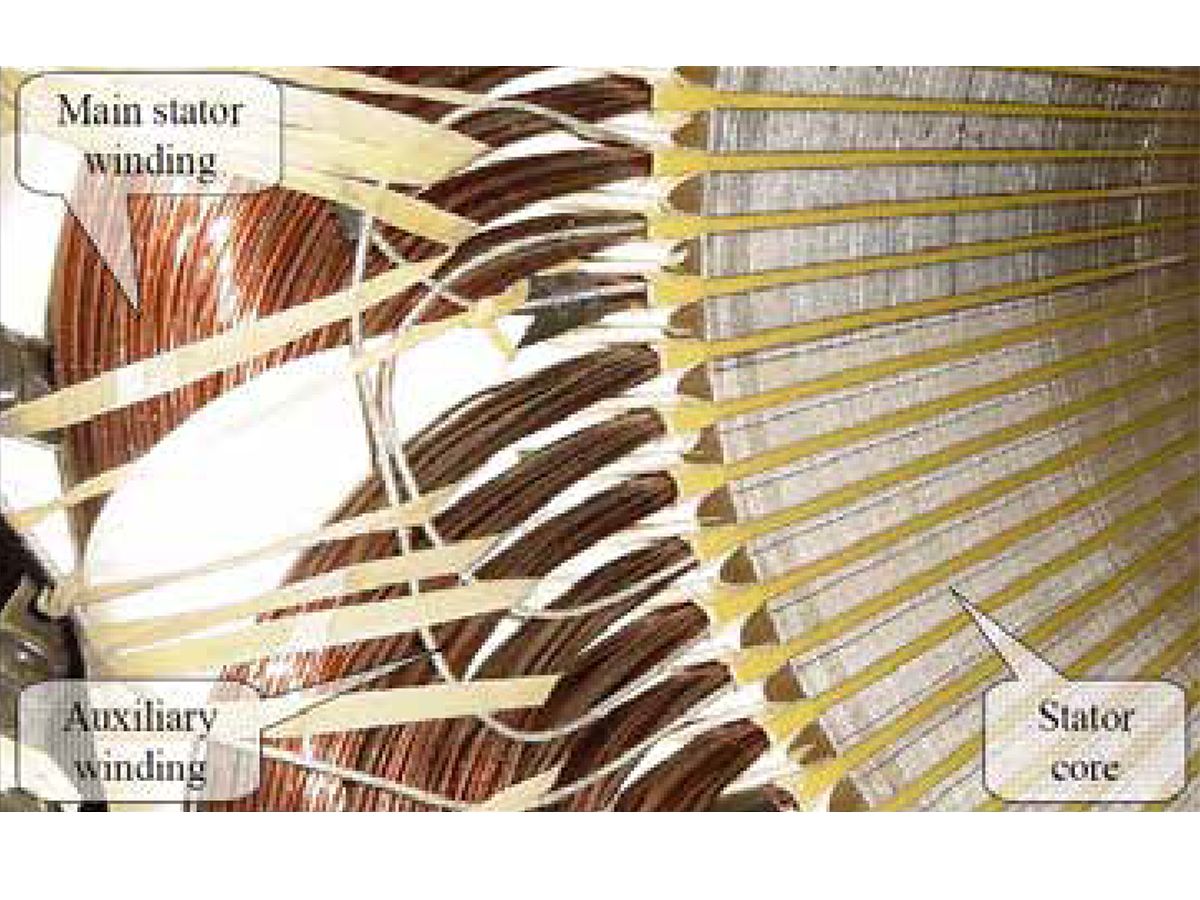
Figure 1. IE Low Voltage Stator Winding
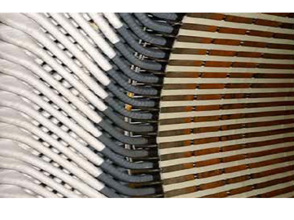
Figure 2. IE Medium and High Voltage Stator Winding
The two auxiliary windings are connected in series to the three-phase power input of the voltage regulator, as the power source for the excitation system. One auxiliary winding produces a voltage proportional to the output voltage of the unit (shunt characteristic). The other acts like a current transformer and produces a voltage proportional to the output current of the unit and is a function of the applied load (compound characteristic – booster effect). The two outputs are combined inside the voltage regulator and provide a constant power source. Figure 3 below shows the interconnections between the various components of the alternator with IE.
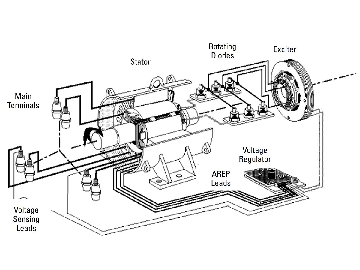
Figure 3. Simplified schematic showing the main components of an IE alternator
Figures 4 and 5 below provide additional information on how the output voltage of the auxiliary windings is related to the load applied to the alternator. The Shunt winding provides most of the normal load excitation current required for the alternator. Its output is constant up to 150-200% of rated load. If the load is increased above these levels, the regulator does not get enough power to maintain the rated output voltage of the alternator, and the voltage will collapse.
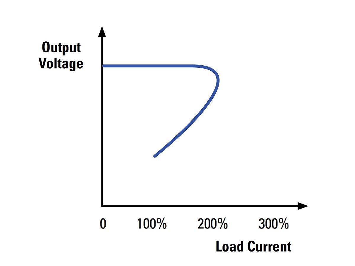
Figure 4. Shunt Auxiliary Winding
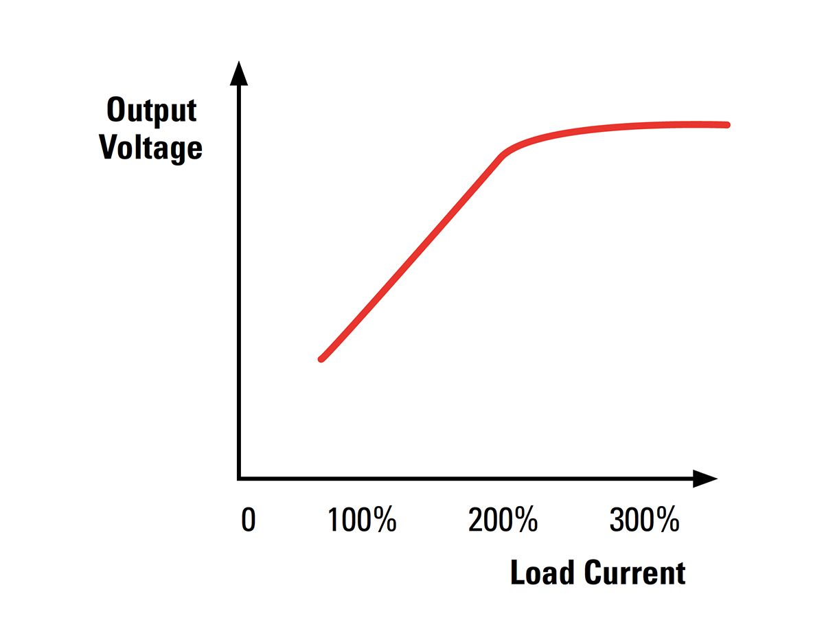
Figure 5. Series Boost Auxiliary Winding
The Series Boost auxiliary winding provides little, if any, excitation at no load. However, its output increases with the load and saturates between 250-300% of rated current. This means that above 250-300% of rated current, the output voltage of the Series Boost auxiliary winding levels off. That leveled value is calculated to be sufficient for the regulator to provide the 250-300% short circuit current capability.
Figure 6 below shows the combination of the two auxiliary windings providing a constant power source for the voltage regulator. Figure 7 below shows the alternator output voltage supported by the combined output of the two auxiliary windings meeting the identical short circuit capability of a PM excitation system.
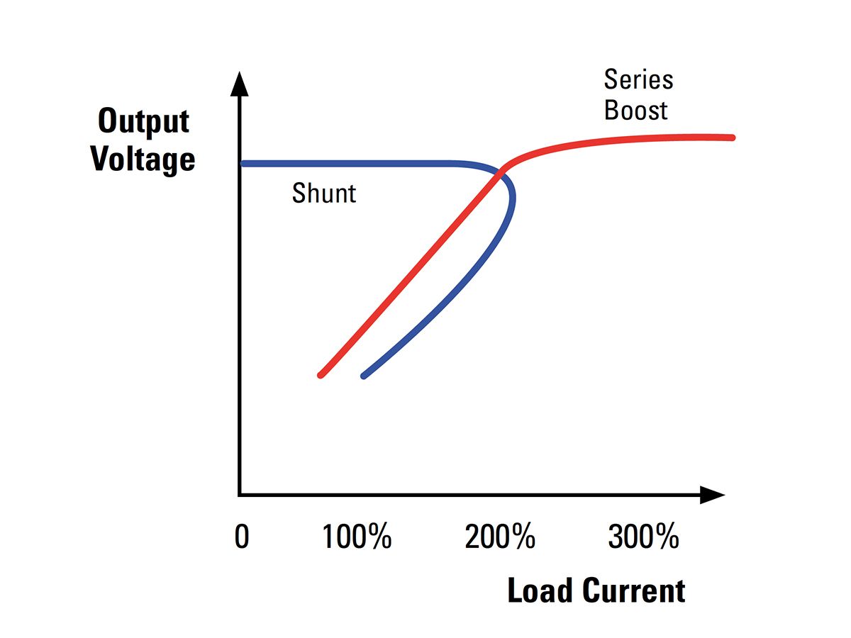
Figure 6. IE Auxiliary Windings
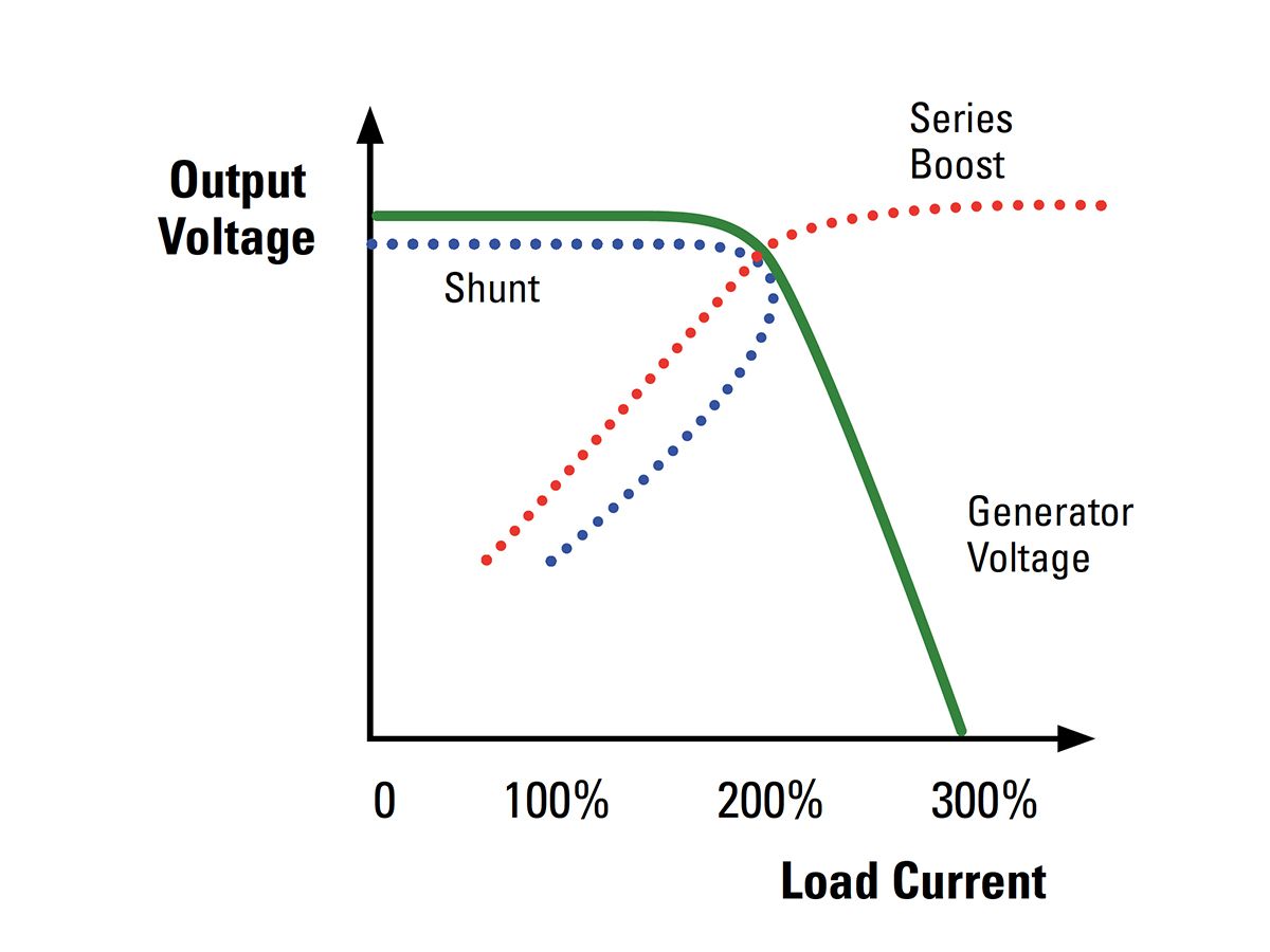
Figure 7. Alternator Output Voltage
ADVANTAGES OF IE ALTERNATORS
A key performance advantage of the IE system is its ability to provide consistent power to the excitation system with all types of load including large non-linear loads, such as those from a silicon controlled rectifier (SCR), an Uninterruptable Power Supply (UPS) or a variable frequency drive (VFD). The inherent ability of the IE system to work with non-linear loads comes from the filtered DC power supply and its power transistor (refer to Figure 8). Non-linear loads create flux distortions that appear in the output of the auxiliary windings. The first stage of the voltage regulator is a full wave three phase rectifier bridge that feeds the power transistor through a large filter capacitor. This filter provides a clean DC source of power for the Automatic Voltage Regulator that is independent of the load distorted output voltage of the alternator. In addition, the transistor is operated in Pulse Width Modulation at a frequency different than the synchronous frequency and, therefore, prevents load SCR tracking. The ability of the IE system to provide consistent power with non-linear loads does not replace the normal consideration to the sizing of the alternator and the effect of the voltage harmonics to the stability or performance of the alternator itself.
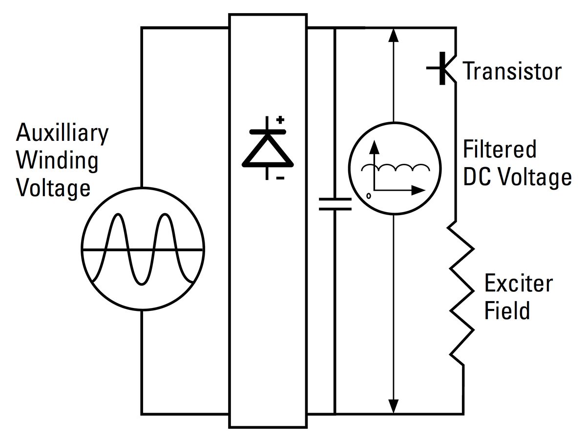
Figure 8. Excitation Schematic for IE
The IE excitation system also demonstrates advantages with linear load application. The constant power supply provided by the auxiliary windings gives the alternator excellent transient performance with load fluctuations, such as occur with large motor starting requirements.
In some standby applications where a generator set is likely to have very long periods of non-operation, there can be concerns of losing residual magnetism in SE alternators to an extent that the system could not operate. To obviate that concern, a PM is often selected which has intrinsic voltage build-up. The same concern could also apply to IE alternators; however, all Cat SR5 IE alternators; include permanent magnets embedded within the exciter field to improve voltage buildup and/or guard against its loss. These embedded permanent magnets in the SR5 IE alternators remove any concerns of loss of residual magnetism.
With all of the advantages of the increased fault current capabilities provided by the IE system, some utilities prohibit machines having a high short-circuit capability to be operated in parallel with their network either during bumpless re-transfer or continuous cogeneration or peak shaving. The IE system is designed with an additional feature to work with these requirements; the short circuit current capability can be disabled during parallel operation with the utility and fully turned on during standalone operation for maximum performance. This allows the IE system to exhibit the best characteristics for the application, even if the application is dynamic.
Standard IE features which are not available with SE alternators include the immunity to non-linear loads, the excellent motor starting, and the short circuit current capability. The IE provides these features with no additional components and within the same physical envelope of an SE alternator, unlike the PM systems. The IE system should be considered a superior performing system to SE and should be considered an identically performing alternative to PM for fault clearing and motor starting.
SUMMARY OF IE ADVANTAGES
- Excellent motor starting capabilities
- Superior performance under loads with high harmonic distortion compared to SE
- Increased performance under load variations compared to SE
- 300% of rated 60 Hz current (250% of 50 Hz current) sustained short-circuit current for 10 seconds
- Guaranteed voltage buildup at startup for all Cat SR5 IE alternators
- Shorter envelope over conventional PM
- Fewer components, therefore lower risk of failure compared to conventional PM
- Easier access to the rectifier bridge for monitoring and maintenance