
Sign In
Welcome! Sign In to personalize your Cat.com experience
If you already have an existing account with another Cat App, you can use the same account to sign in here
Register Now
One Account. All of Cat.
Your Caterpillar account is the single account you use to log in to select services and applications we offer. Shop for parts and machines online, manage your fleet, go mobile, and more.
Account Information
Site Settings
Security
Excitation Selections
Bryan Snyder
Electric Power, Caterpillar Inc.
ABSTRACT
When specifying a generator, it is often easy to overlook one of the most critical parts, the excitation system. Without the excitation system, you will not be able to produce power, and without the right excitation system, your generator may not perform as expected. Selecting the wrong excitation system could lead to early maintenance issues, inability to support large loads, or even could make it difficult to coordinate all the breakers on your site. So, what is an excitation system, and how do you know if you have selected the right one? This paper will provide an overview of the basics of excitation, highlight the differences between the systems, and provide insights on ways to improve the specification process, which will help balance performance and cost goals for your project.
Generator Basics
An electric power generator works by passing a magnetic field across a wire to induce a current in the wire. In most generators the magnetic field is produced in the rotational part of the generator, identified as the Main Rotor. The wire, or armature, is contained in the stationary part of the generator, identified as the Main Stator. The speed at which the magnetic field crosses the wire determines the frequency of the generated current and is controlled by the prime mover, or engine. The strength of the magnetic field will, in part, determine the voltage and is controlled by the excitation system.
The excitation system generates the magnetic field in the Main Rotor by passing a DC current through the Main Rotor windings. The two methods primarily used for generating the DC current are referred to as Direct Excitation and Indirect Excitation. In the Direct Excitation method, the Voltage Regulator draws power from the Main Stator and converts it to DC current. The DC current from the Voltage Regulator is passed directly into the Main Rotor through a connection using Brushes and Slip Rings. The direct connection with the Main Rotor enables these systems to provide large DC currents, which provides excellent performance associated with large motor starting loads or highly transient loads. The challenge with this type of system is the brushes could require significant maintenance and if not properly maintained could be unreliable.
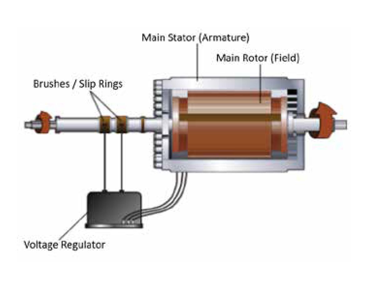
Figure 1: Direct Excitation Generator
Most modern generators utilize the Indirect Excitation system which has removed the brushes and therefore is also referred to as a Brushless generator. The Indirect Excitation systems require a separate alternator known as an Exciter to be connected to the shaft of the Main Rotor. The Exciter will generate the necessary current for developing the magnetic field. The Exciter works backwards from the main portion of the generator in that the Exciter Stator produces the magnetic field and the Exciter Rotor spins within the field to generate the current. In the Indirect Excitation system, the Voltage Regulator only needs to generate the necessary voltage needed by the Exciter Stator and therefore can be much smaller than the Direct Excitation system. The current from the Exciter Rotor will pass through a Rectifier Bridge that is connected to the Main Rotor shaft to be converted from AC current to DC current, which is used to generate the magnetic field within the Main Rotor.
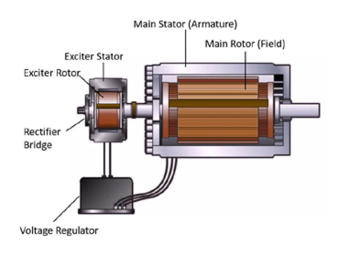
Figure 2: Indirect Excitation System
EXCITATION POWER SOURCES
With an Indirect Excitation system, the power source for the Voltage Regulator is critical for determining the best performance for the system. When large loads are applied to the generator, requiring large amounts of current from the Main Stator, the output voltage will drop. More power is required from the excitation system to boost the magnetic field in the Main Rotor and maintain the voltage at the output of the system. The source for providing power to the voltage regulator, and thereby the excitation system, are typically separated into three primary methods.
SHUNT (SELF-EXCITED)
The simplest method for generating the excitation power is considered the Shunt method, or Self-excited. It is referred to as Shunt because the output windings of the Main Stator are arranged to provide a Shunt Winding which divides the output armature current from the Main Stator and provides a portion of the current to the voltage regulator. The Shunt Windings provide both the AC power and the sensing requirements for the voltage regulator, as shown in Figure 3. The voltage regulator will determine how much excitation current is required based on the input received through these wires. Because there are no additional external sources of power as standard with these systems, they are also referred to as Self-excited.
In a typical operation with a Shunt system a residual magnetic field will be present within the Exciter and Main Rotor of the generator. This field remains within the system from the previous operation and will enable the generator to build up current as it starts. Because these systems are dependent on the residual magnetic field, their ability to start and accept loads quickly may be less as the residual magnetic field decays over time. Regular maintenance and operation of the system will improve this performance.
In some cases, the residual magnetic field could decay to the point which the system could not operate. In this case, the field is required to be “flashed” with power from an external source by a maintenance engineer. This is typically considered an extreme case as the magnetic field resides within an unoperated generator for a considerable time and can be avoided with a regular testing and maintenance schedule. The length of time the residual magnetic field exists will be dependent on the construction material used and other environmental factors.
After starting, the Shunt system will continue to draw power and sensing from the shunt windings on the output of the generator. Any disturbances created from the loads connected to the output of the generator will be apparent on the connections to the voltage regulator.
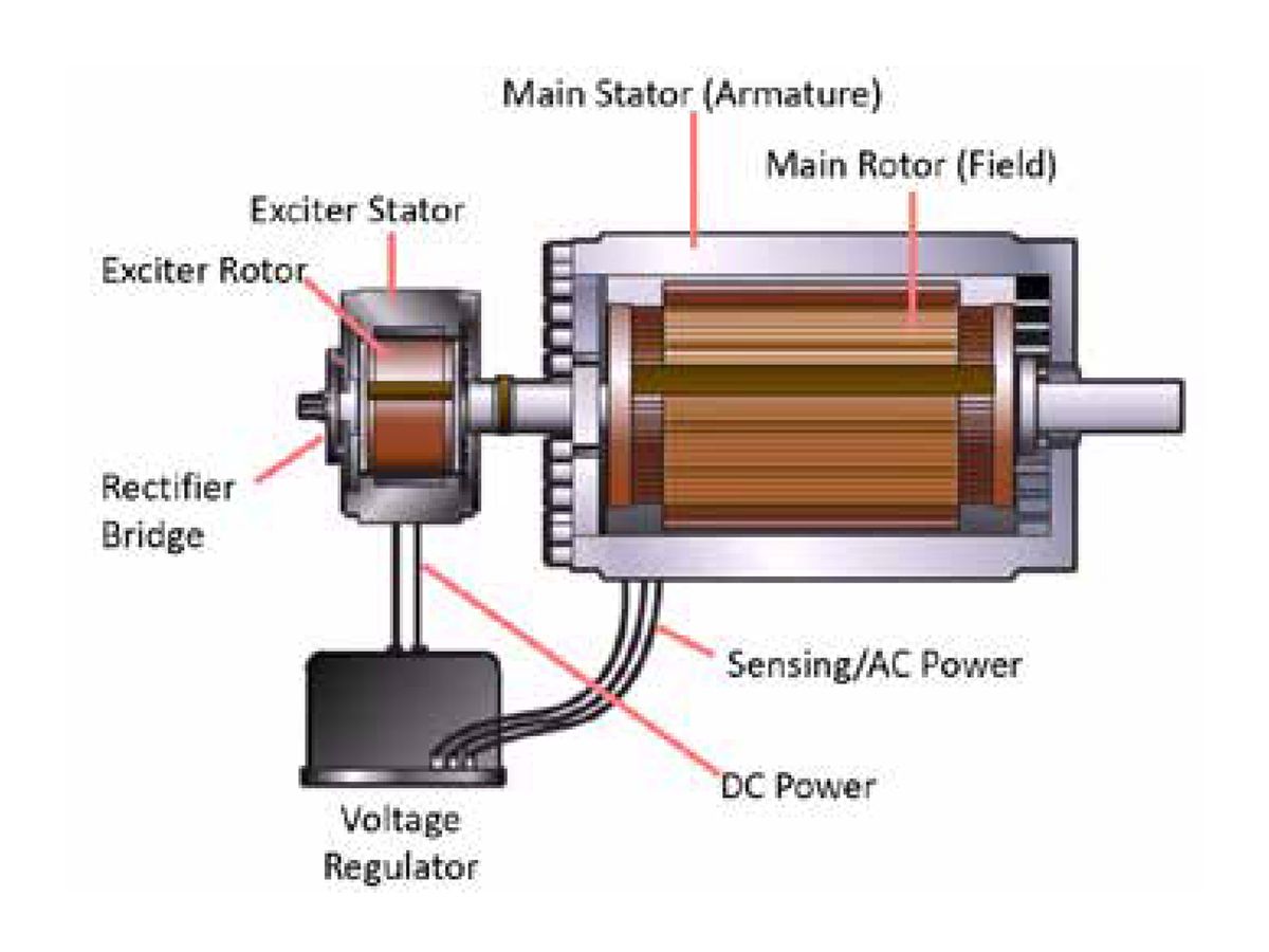
Figure 3: Shunt or Self-excited Excitation System
This can create disturbances with the voltage regulator both for sensing accuracy and the ability to provide consistent power to the Exciter. Highly non-linear loads, such as UPS or VFD powered motors, may cause significant harmonics, which could impact the operation of a Shunt system.
When a large load demand is required from a Shunt excited generator, such as with a large motor starting, the drop associated with the output power available from the generator reduces the ability for the voltage regulator to provide the necessary current to increase the magnetic field. Because of the drop in the magnetic field, the voltage will drop and the recovery back to nominal values will be slower. This is also the case when a fault occurs and the voltage on the output of the generator will collapse; the Shunt system will rapidly drop the available current being produced.
This rapid drop in current may be desirable in some designs as it acts as a natural barrier to an overcurrent event which may damage the generator or other components in the system. In a simple backup application with a simple protection scheme, a Shunt system can be a cost-effective solution. However, in applications where large motor starting currents or high fault currents are desirable, an externally powered excitation system would be more desirable.
PERMANENT MAGNET GENERATOR (PMG)
The most commonly requested externally powered excitation system is a Permanent Magnet Generator (PMG) excitation system. The PMG excitation system adds a generator that uses permanent magnets in the rotor to generate a field and a stator where the power is generated. The PMG is the source for the current provided to the voltage regulator. The use of the permanent magnet elements within the PMG eliminates the concerns related to the need for a residual magnetic field which occur with a Shunt system. The PMG should never need to be flashed to restore the magnetic field and provides intrinsic voltage buildup to support current demand much faster during startup as compared to that of a Shunt system.
During normal operation of the PMG system, the excitation current is continually sourced from the PMG while the sensing remains from the output of the generator. This will allow a PMG excitation system to provide a faster response to a large load acceptance, like a motor starting, because the PMG is able to continue to increase the current to support the excitation system without impact from the load on the generator. Further, the PMG system can provide significantly more fault current than a Shunt system and can maintain the current for a longer period. This is an advantage in large systems with multiple levels of protections to allow for simplification with the coordination of the protective devices.
The primary disadvantages of the PMG system relate to the additional parts required. The PMG will add length to a generator package and can also reduce the statistical reliability of a system as it provides additional parts which could fail. The PMG will also add additional cost to the overall system.
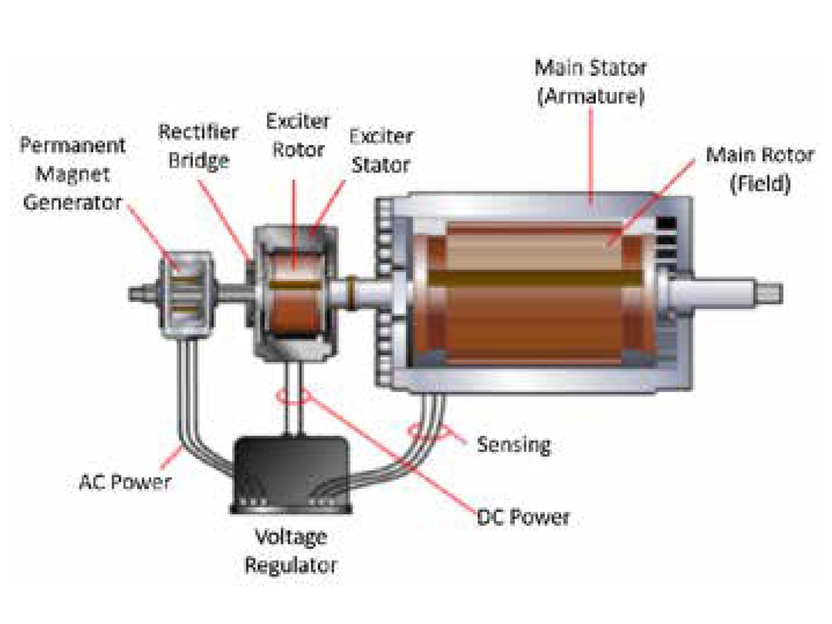
Figure 4: Permanent Magnet Excitation System
INTERNALLY EXCITED (AREP)
The final excitation system which is often overlooked is also a separately powered excitation system and is referred to as Internally Excited or Auxiliary Winding Regulation Excitation Principle (AREP). The Internally Excited system uses a series of Auxiliary Windings which are inserted into the Main Stator of the generator during construction. The Auxiliary Windings are sealed within the system during the insulation process; however, they are electrically isolated connections from the output of the generator.
With the Internally Excited system, the AC power is provided without impact from the output load of the generator just like the PMG system. The separate power source allows the Internally Excited systems to support high power demands quickly and to meet nearly identical performance to the PMG system for motor starting and short circuit current requirements in most designs.
Caterpillar provides further enhancements with many of their Internally Excited generators through the addition of permanent magnet inserts within the exciter field. These permanent magnets enable the Internally Excited generators from Caterpillar to have improved voltage buildup and eliminate any concerns related to a need for residual magnetism to support the startup of the generator. For more information on Caterpillar’s specific Internally Excited systems, see the Caterpillar white paper, LEXE1672 “Cat® Internally Excited (IE) Alternators.”
The Internally Excited systems from Caterpillar provide nearly identical performance to the traditional PMG excitation systems with the advantage of fewer components, which means improved reliability and shorter length.
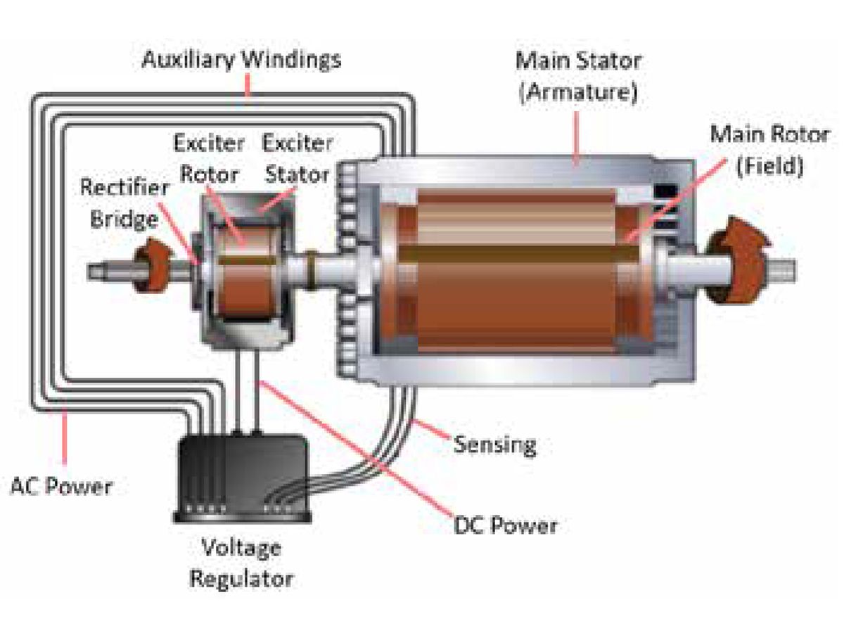
Figure 5: Internally Excited or AREP System
SUMMARY
Understanding how the excitation system of your generator performs can help with making better decisions on the options available to you. The excitation system provides the basis for all the power generated from the generator and will play a large part in determining the overall performance. A typical specification for a generator purchased today will be defined as a brushless, indirect excitation system to ensure low maintenance and reliable performance. However, equally important consideration should be had when selecting the source of power for this excitation system.
For a small backup system that will be regularly maintained, a lower-cost Shunt or Self-excited system may be the optimal choice. This is what is used on most home units and will work for a general use application with minimal risk. If your application is more critical or is in an area where regular maintenance is more difficult, considering a separately powered excitation system will be a better choice.
When evaluating the two options for separately powered excitation systems, consider that the PMG and Internally Excited systems from Caterpillar have identical performance characteristics for fault clearing and motor starting.
The integrated permanent magnets with the Caterpillar Internally Excited systems allow both designs to provide reliable initial magnetization of the system. The primary difference between the two systems is the additional components within the PMG system. While this does allow the PMG to be maintainable, it also reduces the statistical reliability and increases the cost of the PMG system.
When specifying a critical generator system which requires reliable startup, high load acceptance, and high fault current capabilities, it would be recommended to include a statement within the specification that allows the manufacturer to select either an Internally Excited or a PMG system. The primary focus of these systems should be the separately powered excitation energy and the ability to provide high fault current, such as 300% of the rated 60Hz current (250% of rated 50Hz current) for 10 seconds.