
Sign In
Welcome! Sign In to personalize your Cat.com experience
If you already have an existing account with another Cat App, you can use the same account to sign in here
Register Now
One Account. All of Cat.
Your Caterpillar account is the single account you use to log in to select services and applications we offer. Shop for parts and machines online, manage your fleet, go mobile, and more.
Account Information
Site Settings
Security
Temperature Rise and Insulation Class Relationship
Bryan Snyder
Electric Power, Caterpillar Inc.
ABSTRACT
Many factors go into the selection of a generator which will impact the cost, performance and life of the product. Two such factors which are directly related, and often misunderstood, are the Temperature Rise and Insulation Class ratings of the generator. Making the wrong assumptions with regards to these factors and their impact on the overall performance of the generator set can lead to oversized generators which drive a disproportional cost as compared to the value they deliver.
To understand these two factors better, let’s first review some of the basics of electricity. As electrical current passes through a wire, losses, primarily attributed to the resistance in the wire, will generate heat. The amount of heat generated will be dependent on the resistance and the amount of current which is being passed. The transfer of this heat into the surrounding structures must be dissipated and will cause degradation of the additional materials over time. Defining the rate of the degradation and developing a standard representation is what has led to the development of insulation classifications.
INSULATION CLASSIFICATION
The insulation classification specifically refers to the thermal endurance of the insulation system when operating at specified rating. The generator windings and rotor components along with the structural parts and the insulating material all makeup the generators insulations system. The insulation classification is rating the ability of this system to dissipate heat generated as current is passed through the copper wires, and the insulative materials ability to withstand the overall temperatures reached.
The National Electrical Manufacturers Association Motors and Generators standard (NEMA MG-1) is one of the standards used by generator manufactures to classify the insulation material. The insulation systems are primarily classified by NEMA into one of four base categories; A, B, F or H. Each category is defined by the insulation systems ability to endure a specified temperature under continuous operation to meet an acceptable life curve.
The allowable temperature rise, as measured by resistance, for each classification is shown in Table 1 for continuous operation along with the ratings for Standby operation, which provides for an additional 25°C rise. The standard defines Standby operation as applications where the generator is an emergency back-up power source.
All NEMA MG-1 ratings are based on an assumed ambient temperature of 40°C with allowances provided for variations in the ambient and altitude conditions along with thermal margins based on measurement devices. The chart in Figure 1 displays the total temperature allowable when measured by resistance or with measurement devices embedded in the windings for generators over 1563kVA and 7000 volts or less. The embedded devices provide an additional rise in temperature due to potential hot spots occurring at the measurement location. Figure 1 shows the total temperature for the Class H insulation for continuous duty as being 180°C.
The International Electrotechnical Commission’s Rotating Electrical Machines standard (IEC60034) is the standard primarily used by manufacturers outside of North America and provides similar ratings as NEMA MG-1, shown in Table 2 from edition 13. The standards are not entirely identical with regards to their provisions. For example, IEC has eliminated the Class A insulation, added a Class N insulation, and provides different provisions for Standby operation, however the base temperature rise and allowances for embedded detectors are the same. Again, the intention of both these standards is to indicate the temperature rise in which an insulation system provides suitable thermal endurance.
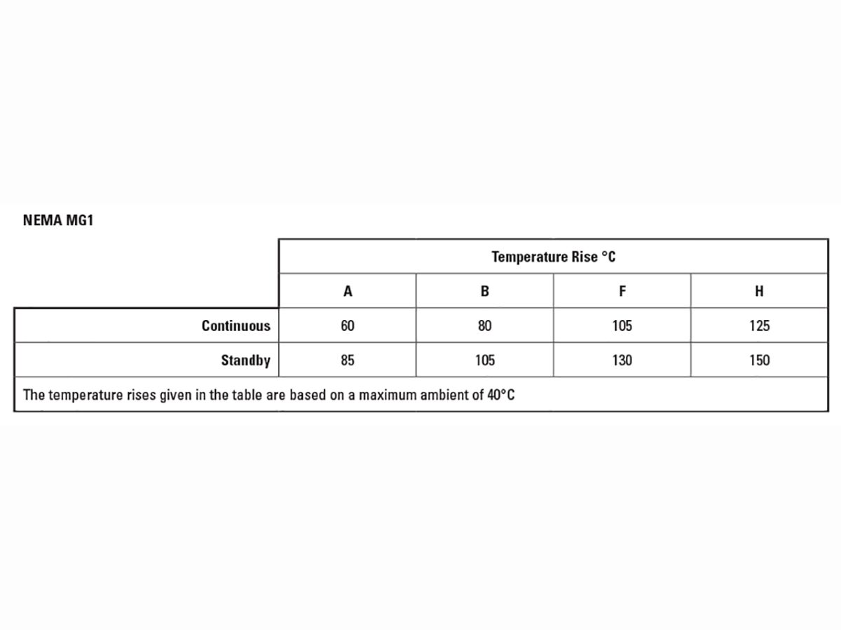
Table 1: NEMA MG-1 Insulation Classification
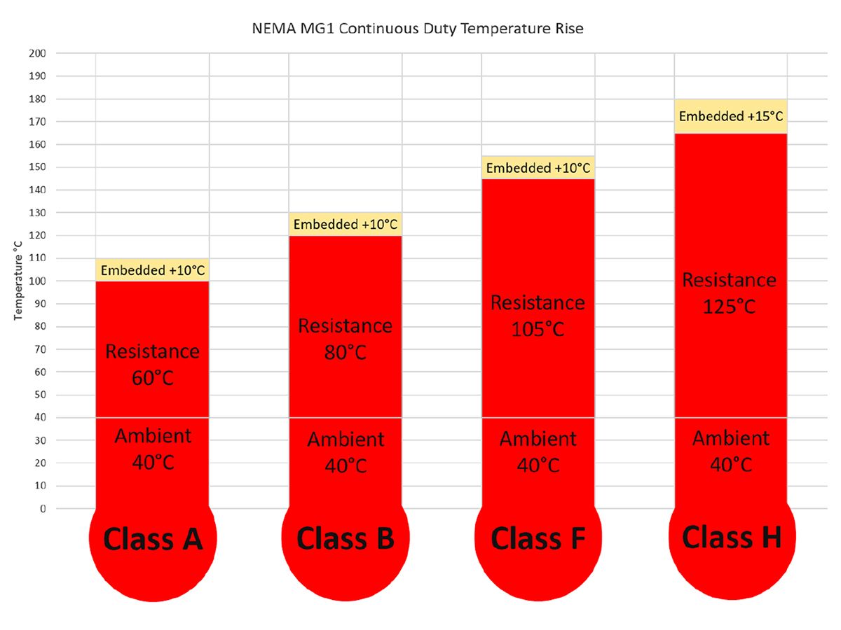
Figure 1: NEMA_MG_1_Temperature_Rise with Allowance

Table 2: IEC 60034 Insulation Classification
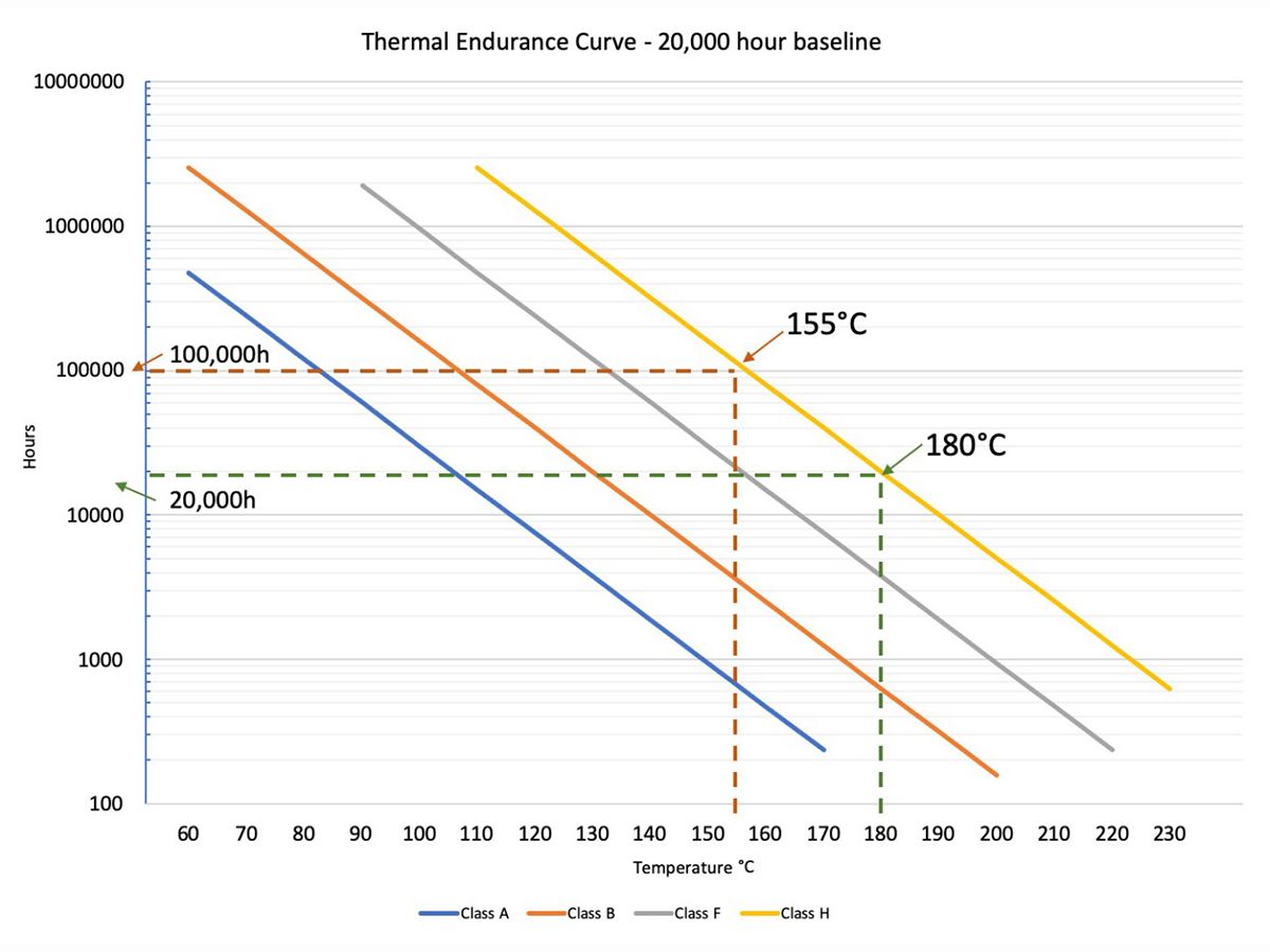
Figure 2: Thermal Endurance Curve Comparison

Figure 3: Thermal Endurance Curve with Standby Temp added
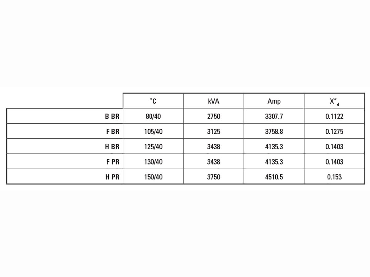
Figure 4: Generator Ratings by Temperature Rise (BR=Base Rating/Continuous, PR=Peak Rating/Standby

Figure 5: Generator ratings with different windings

Figure 6: Generator ratings with different rotors
THERMAL ENDURANCE
So, what is “suitable thermal endurance”? Thermal endurance is not specifically indicating at what point an insulation system will fail, but more indicating when the thermal breakdown of the material could be expected. There are numerous stresses placed on an insulation system within a generator from Electrical, Thermal, Mechanical and Environmental factors. All of these factors work both independently and together to degrade the overall life of the insulation system and may eventually lead to a failure. The thermal endurance of the system uses accelerated life testing along with real world historical analysis to rate the materials used within the insulation. The materials are typically expected to meet a baseline of 20,000 hours of continuous operation before degradation. From this baseline a Thermal Endurance Curve can be developed using the Arrhenius equation, also known as the Rule of 10. This rule states that for every 10°C decrease in temperature, the insulation life will double. The Thermal Endurance Curve in Figure 2 demonstrates the endurance related to each of the four insulation classes.
As highlighted by the dashed lines in Figure 2, the curve demonstrates the thermal endurance of a generator with a Class H insulation operating at 180°C (40°C Ambient + 125°C Rise + 15°C Thermal Margin) is 20,000 hours. The same generator with Class H insulation operating at 155°C (40°C Ambient + 105°C Rise + 10°C Thermal Margin) should be expected to have a thermal endurance in excess 100,000 hours. Comparatively, if a generator with a Class F insulation were to operate at 155°C it would be expected to have a thermal endurance of 20,000 hours. Understanding the Thermal Endurance curves help when evaluating generators of different insulation classifications.
SPECIFYING INSULATION CLASS
Often a customer specification for a generator will state both an insulation classification as well as a temperature rise for the generator. It should be recognized that the temperature rise should be proportionally aligned with the insulation class. That is to say, when a specification requests a Class F Insulation with a 105°C temperature rise over a 40°C ambient per the NEMA MG-1 standard, an acceptable alternative offering would be to provide a Class H insulated generator at a 125°C temperature rise over a 40°C ambient. This is possible because the generator will provide the same thermal endurance. If the 105°C rise is used with the Class H insulation the customer will be paying for 100,000 hours when they are expecting 20,000 hours. Additionally, considerations should be made when specifying for a standby or continuous operation application, to align with the allowances within the standards. When using the NEMA temperature rise of 180°C (40°C + 125°C + 15°C) for Class H continuous operation, as shown in Table 1, the expected endurance would be 20,000 hours as shown previously on Figure 2. If the application is expected to be a standby application an allowance of an additional 25°C should be provided within the specification. The additional 25°C would provide a total temperature of 205°C (40°C + 150°C + 15°C) for a Class H standby operation. As shown on Figure 3, the expected thermal endurance for the standby application would be 4,000 hours. In a standby application, which is typically expected to operate less than 200 hours a year, this would be a difference of 100 years to 20 years of operation. While the thermal endurance is not an absolute with regards to the life of the generator, it does indicate an increased robustness of the overall generator design, which could drive additional cost where the value is not recognized.
SPECIFYING TEMPERATURE RISE
Temperature Rise is not always used in customer specifications exclusively to indicate the thermal endurance of the generator. Often a specification will use a lower temperature rise with the assumption this will provide a more robust generator with regards to performance. This assumption will work in most cases but could be a costly means to achieve the desired results. As stated previously, when electrical current flows through a wire, heat is generated. The resistance of the wire and the amount of current being passed, in part, determine how much the temperature of the wire will rise. Further, the transfer of heat to the materials around the wire along with their ability to dissipate the heat will determine the overall temperature rise of the alternator. Generator manufacturers use the different temperature rises to classify the ratings of the generator based on the flow of current. The same generator may be used at multiple different temperature rises to achieve different ratings as indicated by the data from a single generator in Figure 2. This same generator may be used in applications from 3750 kVA Standby to 2750 kVA Continuous.
Notably by altering the rating of the generator, which lowers the amperage supported, the Subtransient Reactance (X”d) of the generator is also lowered, because it is a ratio related to the rated current. Subtransient Reactance is also used to indicate the electrical robustness of the generator. A lower Subtransient Reactance will provide more available current during the initial demand enabling the generator to respond faster to changes in load. This is often referred to as being a “stiffer source”.
The lower Subtransient Reactance is made possible with the lower temperature rise because more copper is available to provide current than is typically being used. This additional copper is available during the initial demand for energy and makes the generator more responsive. Another way to increase the amount of copper available within a generator is by changing the winding methods. By changing a generator from a Random Wound to a Form Wound generator, as shown in Figure 5, you increase the available copper without impact to the temperature rise rating. This reduces the Subtransient Reactance, providing better performance.
While changing from Random Wound to Form Wound may increase the cost of the generator, it is possible that the increased cost will be less than increasing a temperature class which could require a larger overall generator. There are also methods to improve the generators performance which may actually lower the cost of the generator. The Table below shows two generators with the same temperature rating. Both are Form Wound generators with the same frame sized stator.
The difference between these generators is in the design of the rotor. The changes within the design of the rotor enable Generator B to provide 2% better Subtransient Reactance, but the real value is in Generator B being nearly 20% less cost than Generator A. Due to the changes, Generator B does have less Leading Power Factor capability than Generator A, however this may be acceptable for many applications and provides a significant cost advantage.
SUMMARY
The insulation class and temperature rise of a generator are critical factors that directly influence generator designs and should be considered when drafting requirements specifications. The insulation classification of the generator will determine the materials used to insulate the generator and when combined with the temperature rise targets will provide an expected thermal endurance of the generator. A customer can use this information to generally predict the scale of expected life related to thermal wear and develop an equivalent baseline between products from different manufacturers.
Temperature rise is also often used in specification to identify the robustness of a generator with relation to performance, however this can be a costly method for delivering improved performance. When specifying for performance it would be better recommended to use factors directly related to the performance being sought. For example, if generator response is desirable using factors such as motor starting, or Subtransient Reactance values would allow the generator manufacturer to provide products which meet the desired effect with a potential for less impact on cost.