
Sign In
Welcome! Sign In to personalize your Cat.com experience
If you already have an existing account with another Cat App, you can use the same account to sign in here
Register Now
One Account. All of Cat.
Your Caterpillar account is the single account you use to log in to select services and applications we offer. Shop for parts and machines online, manage your fleet, go mobile, and more.
Account Information
Site Settings
Security
Updating Data Center Power Systems
Chad E. Dozier
Market Development Consultant
Electric Power Division
INTRODUCTION
A Fortune 500 company with an aging data center was experiencing challenges to the reliability of power in its facility. There was an obvious need for reliable emergency power due to sporadic power outages at the grid, and the data center had experienced failures in its backup power system when switching over from one source to another. Additional concerns included new regulatory requirements that had been put in place after the data center was built and high levels of energy consumption, which were significantly above what was intended when the data center was originally constructed. Built in the 1970s, the data center was responsible for managing 60 percent of this global organization’s data. If the data center were to have a complete loss of power, it could cost the company as much as $4 million per hour.
The data center also had several vulnerabilities. It was using outdated Uninterruptible Power Supply (UPS) technology, as well as outdated configurations and procedures. It had experienced failures in switchgear when transferring loads from emergency power back to utility power. The data center was using manual switchgear to transfer loads, which was labor-intensive and introduced the possibility of human error: it would take four to five people to complete the switching process and required a high level of concentration and coordination.
ANATOMY OF A DATA CENTER
In the mid-1970s, the Fortune 500 company designed a new data center building from the ground up that was commissioned in 1978. The data center required 100,000 square feet of space and was supported by four Cat® D399 diesel generator sets. Both sides of the UPS system were fed from this single bank of generator sets. In the early 1980s a fifth generator set, a Cat D399, was added, and in the late 1980’s a second bank of generator sets was added, three Cat 3516s, that was not immediately tied to the UPS system. Each bank now had a rated capacity of approximately 4500 Kw. The generator sets were configured in two separate rooms – five generator sets in Side A and three generator sets in Side B. Critical data center support system – chilled water systems, MCUs (Modular Cooling Units) and Building Monitoring systems – were split between the two generator banks. In the event of a power failure, critical building infrastructure could be maintained so that data center operations would continue without interruption.
The original UPS system was replaced in 1995 when a new UPS system was moved from another facility where construction had been halted. Although the new system had never been in operation, it was approximately two years old at installation. Each UPS side consisted of a system cabinet and three redundant power modules. Only the UPS was replaced with none of the switchgear or single source for emergency power changed. This UPS was referred to as UPS 1 (A side) and UPS 2 (B side) and was sized to redundantly support the entire data center load.
By 2008 the existing UPS system was reaching maximum capacity and a second UPS system, ATS and all associated switchgear were added to meet the increased demand. The new UPS system split the A side and the B side between the separate diesel banks and it was referred to as A1.UPS and B1.UPS. This established a System + System redundancy from the emergency power source to the IT load, but the switchgear lacked any automation. To switch the UPS load to one side for system maintenance required a complex manual procedure and a very knowledgeable staff.
The original UPS system still had both the A side and B side tied to the same generator bank and required a highly labor-intensive process to switch manually. The switchgear was spread over three floors and required technicians stationed on each floor to manage the process. UPS 1 and UPS 2 had numerous single points of failure and had become difficult to maintain. These legacy units also shared the same physical space presenting a single point of failure that might take out both UPS systems and 40 percent of the data center loads. Therefore, UPS 1and UPS 2 represented a lurking vulnerability within the data center infrastructure.
CATERPILLAR KNOWS DATA CENTERS
When the data center was originally built, the Fortune 500 company chose to use Cat generator sets and ancillary power equipment, and it turned to Caterpillar again for restructuring the power system. The Cat team was able to draw on their vast expertise in power generation from the many industries and global regions they serve to develop a customized solution that would address the unique backup power needs of the facility. For example, the Cat team could implement a solution, or an element of a solution, that had previously been designed by Caterpillar for work in the marine, mining or building and construction industries. Caterpillar engineers worked col.laboratively with engineers from the data center, and together they developed a solution that would use the existing generator sets with the installation of new Cat double conversion UPS systems, new Cat switchgear and new Cat Automatic Transfer Switches (ATS), all of which are compliant with the latest regulations. This decision substantially reduced the cost of the project by about one-third — a project that was originally estimated to cost $15 million was completed for $5.5 million.
The Cat team also helped design the physical layout of the new equipment in a way that streamlined operations and increased efficiencies. In the original data center, equipment was spread over three floors – the UPS systems were on the third floor, diesel generator sets were on the first floor, and the substations and ATS were on the second floor. Not only were the new Cat UPS systems and Cat switchgear more efficient and reliable, they were also more compact than the legacy systems, while maintaining the same high level of functionality. The batteries for the legacy Cat UPS systems were much larger than those for the new ones, and the physical space needed for the legacy ATS was a function of the size of the old switchgear. After completion of the project, each UPS side, ATS and associated switchgear was located within the same room, compartmentalized as was each battery bank.
New equipment for both redundant systems was installed in the same footprint that previously contained just the batteries for UPS 1and UPS 2. All equipment was now housed exclusively on one floor in two adjacent rooms and required 20,000 square feet of space – just one-fifth of the original footprint. This new configuration opened up a significant amount of space in the data center so it could continue to grow at the pace of business.
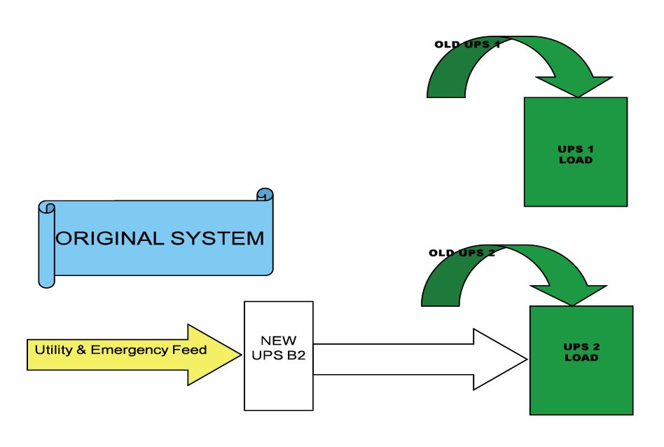
Figure 1
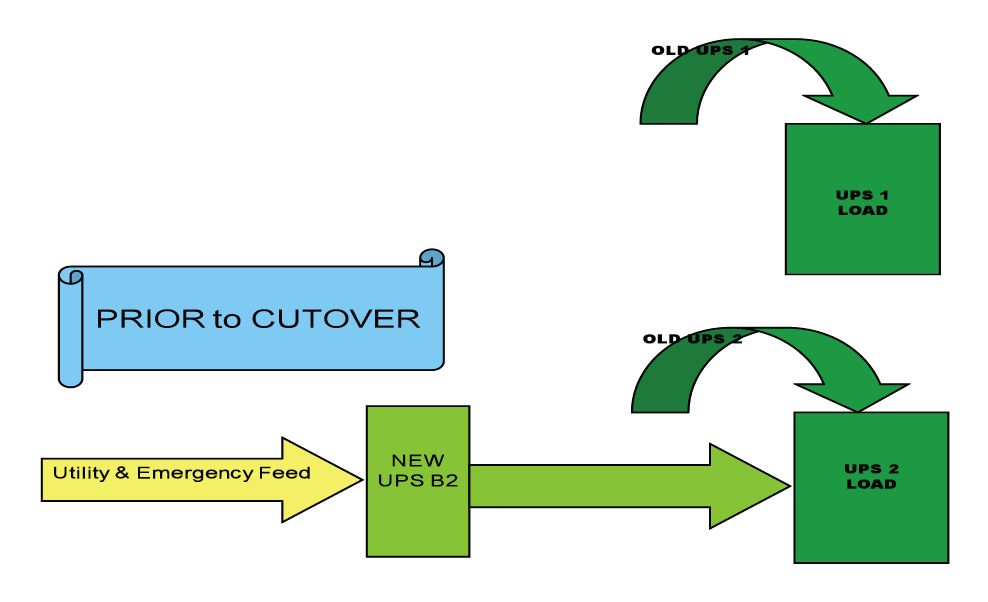
Figure 2
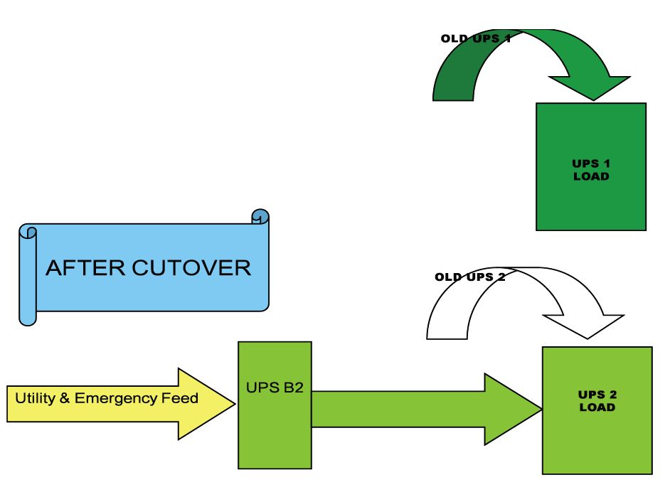
Figure 3
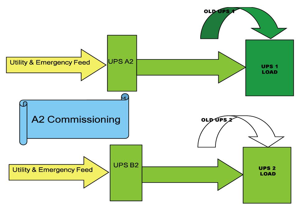
Figure 4
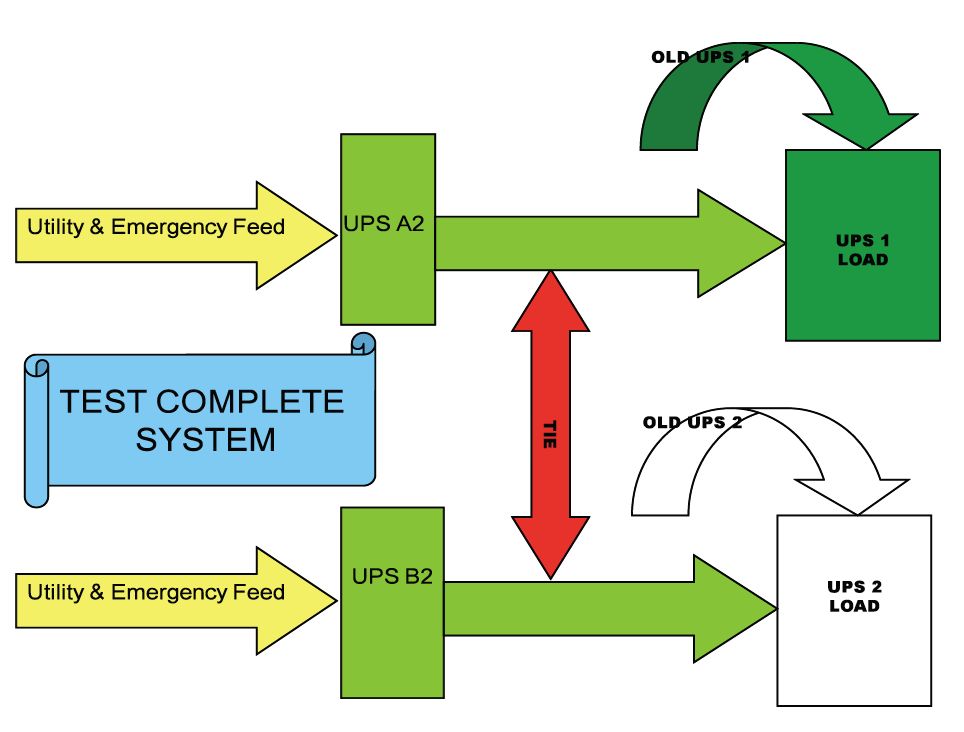
Figure 5
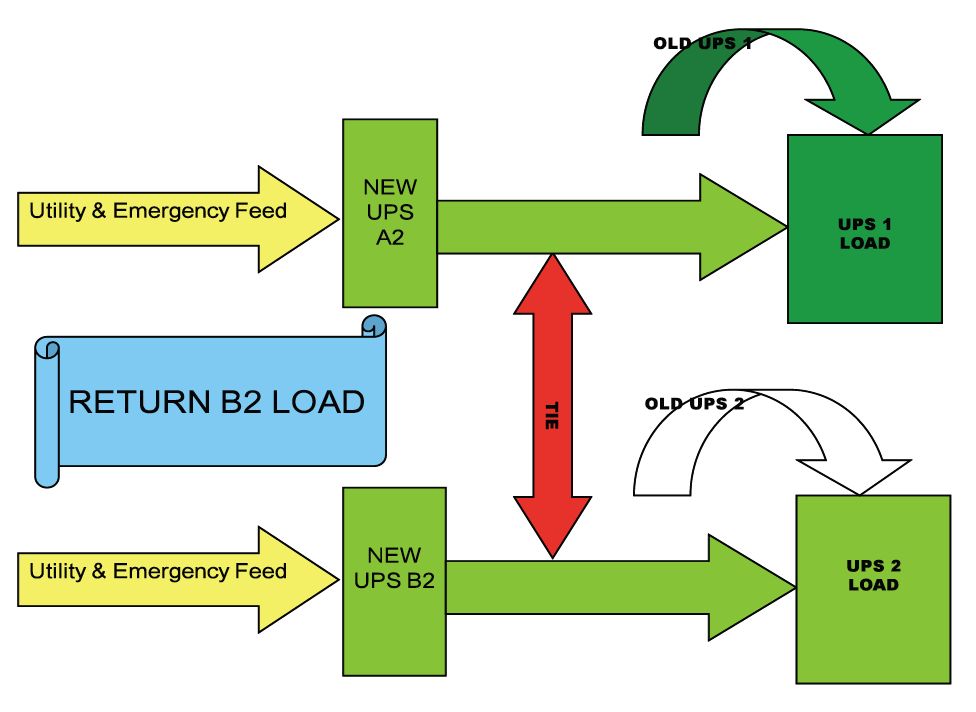
Figure 6
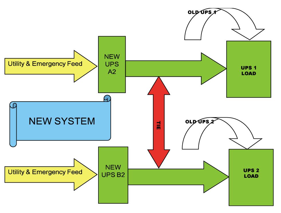
Figure 7
SOLUTION
One of the main goals of the project was to tie together the two banks of generator sets, Side A and Side B, to add another layer of redundancy to protect the data center. Since Side A and Side B each runs at half load, if one bank of generator sets fails (Side A), its load could be seamlessly transferred to the other bank (Side B). The Cat team drew on their experience in the mining industry and recommended making all the controls automated via a touch screen or, if necessary the system could still be operated manually. The touch screen would eliminate the need for multiple personal computers and require substantially less space. Plus, it would significantly streamline actions for the operator, who would need to interface only with a single touch screen information display. It would also simplify the process of switching and require fewer manpower hours.
A significant challenge throughout the changeover process was to maintain 100 percent uptime for critical data center operations while installing the new equipment, tying the two banks of generator sets together and removing the outdated equipment. The Cat team achieved this by creating a backup power scenario, where one bank of generator sets (Side A) served as backup while the new equipment for the other bank (Side B) was being installed and commissioned. No equipment was taken offline until its replacement was fully operational. The only time total redundancy was not available was when the physical output buss was switched from the legacy UPS to the new UPS. The entire process took six to eight hours of continuous work for each side.
Given the data center’s older generator sets and the current need to maintain critical power for a system managing greater amounts of data than that for which it was originally commissioned, two Cat double conversion UPS systems were chosen to replace the two legacy UPS systems. This type of UPS system contains an ample battery backup time to get the generator sets up and running in the event of an emergency.
To begin the process, the new Cat double conversion UPS system for the Side B generator set bank (UPS B2) was installed, commissioned and load tested, while maintaining operation of the legacy UPS system (Old UPS 2) (see Figure 1). The redundant side of the system was still being powered by Old UPS 1 (Side A generator bank). At this point, the data center had two redundant power feeds.
Next, the new Cat double conversion UPS system (UPS B2) was connected and turned on (see Figure 2).
Once it was fully operational, the Old UPS 2 system was taken offline and its many rows of batteries were removed (see Figure 3).
When this step was completed, the second double conversion UPS system was brought in to power the Side A generator set bank during its commissioning process (see Figure 4).
To maintain a consistent source of power, the full power load was distributed to the Side A generator set bank while the changeover was taking place on Side B (see Figure 5). This step facilitated the commissioning of Side A2, which needed to occur before Sides A and B could be tied together.
Tying the two systems together with controls allows either generator set bank, Side A or Side B, to be managed from the same touch screen even though they both operate indepen.dently. This shared point of command enables the two new Cat double conversion UPS systems to “talk” to each other, and to respond with immediacy to a power failure by shifting loads to the appropriate generator set. No matter where the failure occurs, at the grid or at the generator sets, the data center will now always have backup power with this added measure of redundancy (see Figure 6).
Switching from generator set bank Side A to Side B is now fully automated and can be managed simply via a touch screen interface (see Figure 7).
This brings greater levels of efficiency in data center operations, significantly reduces the number of personnel needed to implement the switching process and leads to greater reliability, especially when routine maintenance is performed on the equipment. It also offers scalability in terms of managing ever-increasing amounts of data to support this Fortune 500 company in terms of its future digital growth and the kinds of services it can offer to its dealers and customers.
CHOSING A PARTNER
The Cat team brings an unrivaled element to providing solutions to their customers: their unique perspective, which is based in deep expertise in power generation over a wide array of industries and regions across the globe, as well as detailed domain expertise in your industry to help solve the unique challenges you face. Within this knowledge base is a Cat team member who knows the intimate details of your specific business, and the entire power generation system upon which it relies, and can work collaboratively with you to build the best possible solution to optimize business operations.
December 2013